Geometry inspection of shiny or reflective articles using laser scanner and PSD camera (TRL4)
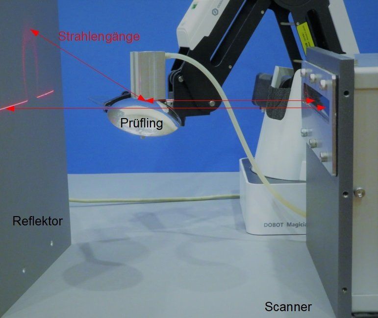
During a laser scan, the laser beams are reflected on the object surface and can be made visible on a screen. The pattern that appears on the screen is characteristic of the surface. By recording with a PSD camera, which records the X and Y center of gravity coordinates as a 2-channel image at any time, the scanning laser beam, which is precisely known at any time, can be clearly assigned to the position of the pattern on the screen. 3D errors in a component lead to an image from the PSD camera that differs from that of a good part. The size of the deviation shown and its position on the component are recorded automatically. By scanning twice or simultaneously displaying it on two screens, the reflected beam can be clearly determined at any time. The 3D coordinates and the angles of inclination of the surface are derived from the precisely known beam directions both during illumination and after reflection on the surface.
Principle of 3D inspection of shiny / reflective articles

- Development, control and optimization of production processes
- Quality control (in production, outgoing goods or incoming goods)
- Shiny and reflective surfaces - also non-planar
- Illumination by means of a laser scanner, imaging of the reflected laser beam striking the object one or more screens by means of a camera(s), which allows a clear assignment of the coordinates of the pattern progression to the progression of the illumination direction at any time.
- Determination of differences in the pattern progression on the screen surface compared to the progression on a reference part and the positions on the object surface where the deviations occur. Determination of the surface inclinations and coordinates with at least two sample recordings (simultaneous or sequential).
Complete inspection of shiny / reflective components for defects, material, coating and shape using a retroreflex laser scanner for illumination and a retroreflective screen.
depending on scanner type from 25 mm to (currently) 160 mm
- Laser scanner for lighting
- One or more screens
- PSD Camera
- 24V power supply
- extremely large depth of field (compared to cameras)
- robust against object displacement
- low effort for adjustment
- Image interface (GiG-E or CameraLink)
- RS-232 interface for parameter setting
Send us your samples for a first free test or let us convince you with a device demonstration in your house!
We would be glas to adapt the sensors to your needs or develop new functions for you.
Patents
- M. Hartrumpf, "Laserscanner-Meßsystem"; DE19806288A1
- M. Hartrumpf, "LASER SCANNER MEASUREMENT SYSTEM"; EP1056987A1
- M. Hartrumpf, "Laser Scanner Measurement System"; US6858836B1
- M. Hartrumpf, "Vorrichtung und Verfahren zur optischen Charakterisierung von Materialien": EP11760701.0
- M. Hartrumpf, "Apparatus and method for optically characterizing materials": US9222879B2
- M. Hartrumpf, C.Negara, Configurable Retro-Reflective Sensor System for the Improved Characterization of the Properties of a Sample";US 2019/0170636 A1
Patents applications
- M. Hartrumpf, C. Negara, "Configurable Retro-Reflective Sensor System for the Improved Characterization of the Properties of a Sample": EP 3 465 145
- M. Hartrumpf, "Verfahren zur Prüfung transparenter, reflektierender oder glänzender Proben mittels Laserscan": DE 10 2023 001 792


